Showing posts with label Solar Vacuum Airship. Show all posts

December 8, 2013

Designing a Geodesic Vacuum Sphere

Previously it was shown that geodesic vacuum sphere is best designed using a boron/epoxy fiber reinforced composite.  Now let's consider exactly how such a sphere is designed and constructed.  Much of what follows comes from Hugh Kenner's Geodesic Math and How to Use It.

First we recall that each face of a regular icosahedron is a regular triangle.  We have subdivided each edge of that triangle f times, where f is the frequency of the structure.  Now if we two dimensions, U1 and U2.  U1 is counted, starting at zero at the top, down the left edge.  U2 is counted straight to the right from that edge.  Each point on the face can be described by U1 and U2.  U1 varies from zero to f, while U2 varies from 0 to U1.
Using these two points we can describe dimensions L, M, and N as follows:
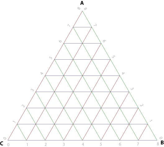
source: phrogz.net


Using these we can describe the location of each node on the face in spherical coordinates:


Each individual member of the structure can be described by its chord factor, which is quite simply its length divided by the radius of the sphere.  So, if we convert from spherical to normalized Cartesian:

Then the chord factor is just the normalized distance between two points:

Any given node has 6 members attached to it, except the vertices which have only 5.  However, if we generate the chord factors moving down and right then we need only generate three (or two) at each point, since the one to the left and two above are already accounted for.

Now let's consider the structural members required.  Consider the force in an individual member.  The whole point of a tensegrity (of which geodesics are a special case) is that all member equally bear the load.  Therefore we can find the force borne by any individual member as simply the pressure times the surface area divided by the number of members:

We set that equal to the buckling criterion to find the area moment of inertia necessary in any individual member based on its chord:
 

If we assume each member is a thin walled tube then we can also find the area necessary, simply by assuming that the structure will fail in compression:

For a thin walled tube the moment of inertia and area are related:
 
So we can find the tube radius and thickness, normalized to radius:
 

We can use all this information to find the maximum possible lifting capacity for a given material and frequency.  Using this spreadsheet that was accomplished.  We find a theoretical maximum lifting capacity of 2.78 kg/m3.
This maximum relies on a large number of very near failure pieces.  It's more reasonable to assume a small number available diameters.  We can assume from this result, however, that a lifting capacity of at least 2 kg/m3 is achievable for a vacuum sphere.

February 20, 2013

Geodesic Vacuum Sphere Materials

Using the equations described in the previous post regarding geodesic vacuum spheres it is possible to determine the utility of materials to building one.  To simplify this a spreadsheet was written to find the optimal frequency for a given material and proposed altitude.  This sheet uses a simplified version of the US standard atmosphere model to estimate temperature and pressure given altitude, then finds density using the ideal gas equation.  Sheet two calculates the left side of the equation derived in the previous post which is compared to the right hand side calculated in sheet one:

Based on the results two materials are selected as potentially useful: unidirectional carbon-epoxy and boron-epoxy composite stringers.  It is observed that even under the maximum possible load pressure, full vacuum at sea level, both materials are still serviceable.  At higher altitudes the pressure difference decreases and the member thickness is allowed to drop, resulting in higher frequency spheres.
At sea level only a frequency of 1 is permissible, however for an airship optimized for cruise above 20km the boron-epoxy is capable of supporting any desired frequency.  A functional limit of 12 is in place to avoid localized buckling.
This sheet also calculates the excess lift produced by a vacuum sphere of the chosen material, in terms of lifted kg per cubic meter.  Lifted mass is possibly the most important result, as it allows further development of the proposal.  A rough layout becomes possible once one can calculate the size of vacuum spheres necessary to lift a given payload or vehicle.
For obvious reasons given the data presented boron/epoxy has been selected moving forward.  For this material the following has been found:
  • sea level: f=1, lift=3.9kg/m3, r/R=0.07
  • 10km: f=2, lift=1.5kg/m3, r/R=0.04
  • 15km: f=4, lift=0.8kg/m3, r/R=0.018
  • 20km: f=12, lift=0.4kg/m3, r/R=0.006
From this point a reference vehicle optimized for cruise at 15km is to be described.  However this information should also be useful for construction of a sea level test article, should materials and facilities become available.
Reference Spreadsheet

June 25, 2012

Potential of a Geodesic Vacuum Sphere

As I said before, a conventional thin-walled pressure vessel would be incapable of bearing atmospheric pressure without weighing more than the air it displaced.  However using the methods described in my previous post on the subject it should be possible to describe a geodesic sphere that can.
Recall that a geodesic shape is an ordinary polyhedron composed of stiff members made to bear only compression forces in one direction.  These members can be kept short be subdividing the faces of the shape, thus preventing the members from buckling.  The final shape is then covered in a strong fabric or shell that bears tensional loads and holds the vacuum.

June 4, 2012

Geodesic Vacuum Spheres

Since a standard thin walled pressure vessel is not adequate to the construction of a vacuum airship it will be necessary to try an alternative system.  Much preferred to thin-walled structures for compression are geodesic structures.  Although geodesics are found commonly in nature and there are many examples of early engineers using similar principles (the Roman arch and dome being examples) they were first described analytically and thoroughly explored by Buckminster Fuller in the 20th century.
Geodesic domes, or braced domes, consist of a large number of members arranged into a regular polyhedron.  Domes typically use a truncated, or cut off, shape rather than the full polyhedron.  For our purpose here the full shape will be used.  Although any regular polyhedron is acceptable, the most common is Fuller's original icosohedron proposal.  An icosohedron is a 3 dimensional shape with 20 equal faces, gamers will immediately identify the basic shape as a 20 sided die.

May 24, 2012

Vacuum Airship Principles

Conventional airships fill a vessel with some gas having a lower density than the surrounding air.  This creates a volume which weighs less than the air it displaces, creating a net upward buoyant force.  A vacuum airship uses a similar principle; however instead of a lighter-than-air gas a rigid vessel is emptied of the air inside.  If the total weight of the displaced air of the interior is greater than the weight of the vacuum vessel then the vessel will experience a net upward force similar to that experienced by the gas filled balloon.

May 19, 2012

Types of Airships

In principle any vehicle that moves through the air without touching land or water can be called an "airship."  Conventionally, however, only those that float through the air as a sea vessel floats on the water are called such.  Distinct from vessels that "fly" or rely exclusively on aerodynamic lift.  For our purposes we will use the term "airship" to refer only to vehicles that use static lift, or buoyancy.

May 18, 2012

Solar Vacuum Airship Abstract and Contest Entry

I've entered my designs for a solar vacuum airship in the Design the Future Contest.  A more detailed writeup will follow, but here is the entry abstract: