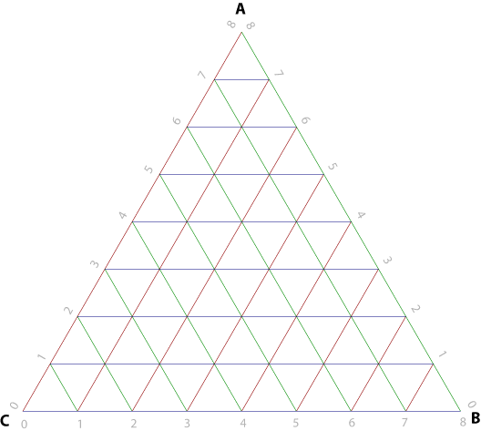
First we recall that each face of a regular icosahedron is a regular triangle. We have subdivided each edge of that triangle f times, where f is the frequency of the structure. Now if we two dimensions, U1 and U2. U1 is counted, starting at zero at the top, down the left edge. U2 is counted straight to the right from that edge. Each point on the face can be described by U1 and U2. U1 varies from zero to f, while U2 varies from 0 to U1.
Using these two points we can describe dimensions L, M, and N as follows:
Using these we can describe the location of each node on the face in spherical coordinates:
Each individual member of the structure can be described by its chord factor, which is quite simply its length divided by the radius of the sphere. So, if we convert from spherical to normalized Cartesian:
Then the chord factor is just the normalized distance between two points:
Any given node has 6 members attached to it, except the vertices which have only 5. However, if we generate the chord factors moving down and right then we need only generate three (or two) at each point, since the one to the left and two above are already accounted for.
Now let's consider the structural members required. Consider the force in an individual member. The whole point of a tensegrity (of which geodesics are a special case) is that all member equally bear the load. Therefore we can find the force borne by any individual member as simply the pressure times the surface area divided by the number of members:
We set that equal to the buckling criterion to find the area moment of inertia necessary in any individual member based on its chord:
If we assume each member is a thin walled tube then we can also find the area necessary, simply by assuming that the structure will fail in compression:
For a thin walled tube the moment of inertia and area are related:
So we can find the tube radius and thickness, normalized to radius:
We can use all this information to find the maximum possible lifting capacity for a given material and frequency. Using this spreadsheet that was accomplished. We find a theoretical maximum lifting capacity of 2.78 kg/m3.
This maximum relies on a large number of very near failure pieces. It's more reasonable to assume a small number available diameters. We can assume from this result, however, that a lifting capacity of at least 2 kg/m3 is achievable for a vacuum sphere.

No comments:
Post a Comment