Before we look at how a spacecraft's structure is put together we need to consider how structures are built at all. Most structures are built in one of two ways: they use a
frame, a skeleton of members to give it shape and strength, or they use
load bearing walls, in which the entire structure's face supports it. Most spacecraft structures use a combination of the two.
A
load is a force which a member is subjected to. There are three forms of simple loads:
tension,
compression, and
shear. Tension loads pull against the member, compression loads push on it. Shear loads push or pull two sides of the member in opposite directions. Materials are generally stronger against compression and tension than they are against shear.
Imagine a block of wood supporting a load above it. Naturally we know that a wider block can support more weight. But all blocks of wood can support the same amount of
stress. Stress is defined as the load divided by the cross-sectional area of the member supporting it, the width and thickness of the block. While a block with a larger area can support more load than a thinner one they can both support the same amount of stress.

When a member is stressed it changes its dimensions. Think about a rubber band, when you pull on it it gets longer and thinner. That's because there's still the same amount of material there was before. So if we compress an object it should get wider and shorter. The change in the length of a member under stress is called the
strain. Strain is defined as the change in length of the object divided by the original length:

When subjected to the same stress a given material will always experience the same strain. This is a material constant, something that is the same for this material no matter the situation. The property that relates stress and strain in a material is called
Young's modulus (or the elastic modulus):

Most materials are
elastic for a while, when deformed they spring back after the load is removed. After a certain amount of stress, called the
yield strength, they are no longer elastic and Young's modulus isn't useful anymore. After the yield stress they are
plastic, their deformation is permanent. Eventually enough stress is applied that they break entirely, called the
ultimate strength. We usually don't want a material to yield, since we want it to keep whatever shape we put it in, so we need to make sure that members aren't subjected to loads above their yield strength.
In the elastic region stress and strain are related by the modulus. After the material yields it enters the plastic region, where force simply goes into deforming it. Eventually it deforms so much that it breaks. Materials with a large plastic region are called
ductile; we can shape them and they remain in their new shape and will resist changing from it. Materials with a small, or no, plastic region are called
brittle; once they yield they break. Counter-intuitive as it may seem a rubber band is brittle, it has no plastic region and breaks as soon as it is over-stretched.
Many common materials have the same properties in all three dimensions: x, y, and z. These materials are called
isotropic. Some materials do not have the same strength or stiffness in all directions, however, and are called
non-isotropic. An everyday example of a non-isotropic material is wood. Wood is much stronger in the grain direction than against the grain, this is because the grain fibers are stronger than the sap that holds them together. Consider also plywood, which is composed of thin sheets of wood glued together. The glue is its weakest point, so the plywood has different properties in all three dimensions: the fiber is stronger than the sap, which is stronger than the glue. Modern fiber reinforced composites are similar. They are stronger in the grain direction than any other, and the matrix holding different plies together is the weakest point.
As simple as the three basic load conditions are, most materials won't actually fail in shear or compression. Under most situations when a material is subjected to a shear load it doesn't actually shear apart, it bends.
Bending occurs when part of a material is pushed in one direction and the rest is pushed in the other. Usually shear happens when these two forces are very close together.
Observe that when the material bends its top half is in compression and the bottom half is in tension. The bending stress in both is the same, but it is in opposite directions. In the middle, the
neutral axis, there is no stress. It goes from negative that value on top to zero in the middle to positive on the bottom. The bending stress depends on distance from the neutral axis, the further away from it the higher the stress.
This is the reason for I-beams. Since there is little stress in the center there is no need for material there. Most of the material is at the top and bottom, where the stress is highest.
Now, consider again the wood column with a load on top. Will it actually get thicker? Usually not unless it is already very thick, most thin member will
buckle when subjected to compression loads. Buckling occurs when part of the material bows out. It is like bending, except that the load pushes in along the axis.
We need to be concerned with
both buckling and compressive failure when loading a column in compression. Just as we need to be concerned with
both shear and bending failure when subjected it to a shear load. Bending and buckling depend on the
moment of inertia of the structure, while compression and shear depend on the area. This means that while the simple load cases (compression and shear) only depend on how much material there is, bending and buckling depend on how it is arranged.
Before we observed that elastic materials spring back into shape when deformed. Picture a spring, when you push it down it bounces back. But before it gets back to where it started it bounces back and forth for a while. Materials that have deformed act exactly the same way, when they bounce back they vibrate slightly for a while. All objects have a range of
natural frequencies that they vibrate at when subjected to a force. The lowest of these is called the
fundamental frequency, it is the one which the object is most likely to vibrate at. Think about a guitar string. When you pluck the string it vibrates. Shorten the string and the pitch gets higher, thicken the string and it gets lower:

The kinds of failure we looked at before come from
static loads. Static loads do not change with time. There are also
dynamic loads, which do change with time. Dynamic loads can be
transients, brief or rapidly changing loads like a ramp up/down or an impact, or
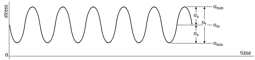
cyclic. Cyclic loads repeat themselves. They subject the member to a force that is time varying, with some maximum, minimum, and average values, and repeats with some frequency:
Ordinarily we would only worry about the peak stress here being higher than the yield stress of a member. However if the frequency of the stress is the same as the fundamental frequency of the member a situation called
resonance occurs. In resonance each time the material gets to the peak of its displacement it is pushed back by the force, pushing it a little further each time. Picture a kid on a swing. By pumping his legs just as gets to the back of his swing he can push the next swing a little further. In a material this pushes the material's deformation further and further each cycle, until it fails. Resonance can cause even small loads to build up to catastrophic displacements. For an excellent reference consider the Mythbusters' attempts to recreate Nikola Tesla's claims to have invented an earthquake machine.
So that's what loads do to a member in a structure. But where do the loads come from? A vehicle in space experiences forces from several sources:
- propulsion - thrust is generally a static load applied by the spacecraft's engines. Engine sputter can also cause small transient loads and the engine itself can vibrate causing small cyclic loads.
- deployment - extending booms or opening apertures creates transient loads on the vehicle.
- thermal - when a material heats it expands, when it cools it shrinks back, causing thermal strain. If it's being held in place then a thermal stress results from holding it back. This can be a static load if the material stays at the new temperature, cyclic if it heats and cools (like a spacecraft moving in and out of sunlight), or transient if the heating is brief.
- internal mechanics - mechanical systems by definition move, they subject some component to force. They are also subjected to some force, as is whatever they are mounted to.
While loads in space can be intense, the larger problem is often launch loading:
- thrust - launch thrust is much higher than the small thrust values used once in orbit. Payload fairings are designed to lessen the g-loading payloads are subjected to, but cannot completely eliminate the force.
- aerodynamic forces - as the launch vehicle moves through the atmosphere it is buffeted by winds. This is generally a transient load, gusts blow briefly, creating high force for a brief time. By design little of this load reaches the payload.
- acoustic and vibration - the entire vehicle shakes during launch and produces extremely powerful sound waves. These in turn cause the vehicle to vibrate.
- staging, separation, and injection - transient loads caused by the launch vehicle discarding unneeded parts during flight.
A spacecraft is composed of two forms of structure.
Primary structure gives the spacecraft its shape and holds all of the systems together.
Secondary structure provides support and mounting for the various systems and subsystems. The secondary structure transmits loads from the systems to the primary structure and reduces loads going to systems.
Forces are carried by members in a structure and transmitted through it. In a load bearing wall the wall carries forces through it, so that most of the wall is under the same load. In a frame supported system each member in the frame carries a force through its length to the joint where it is connected to other members. Consider the simple trusses below:
Each member caries a force through its length. So a horizontal member carries horizontal loads, a vertical member carries vertical loads, and a diagonal member carries some vertical and some horizontal load.
On the ground our goal is to transmit the loads through the structure to the ground. Each member carries the load in whichever direction it can until we get to the grounding points. The ground provides the reaction force, it pushes back in the opposite direction so that our structure doesn't move.
In space there is no ground to bring the load to. If the entire primary structure is subjected to the same force then the structure will move. To prevent the spacecraft from moving we must either cancel or dampen the force. Cancelling a force means applying another force of the same strength in the opposite direction. Like the torque wrench example we talked about back in attitude control, the two up and downward forces cancel so the head doesn't move up or down.
Damping reduces or prevents motion. Damping is usually caused by friction. It happens inside all materials,
internal friction happens when a material vibrates. As it does the vibration also slows until it eventually stops. Any time the structure deforms some of the energy that might have made it move is absorbed instead.
Viscous damping happens when a solid object move through a fluid, like air. Though there is no air resistance in space we can add viscous dampers to reduce motion of components that should remain fixed. The simplest viscous damper is a plunger in a piston of fluid, which resists the motion of the plunger.
Shock absorbers and isolators are in essence simply springs with very high damping. The spring absorbs the shock by compressing or expanding. The damper prevents it from springing back quickly, so the load is transferred up very slowly. Much of the load is also absorbed by the damper so there is less motion.
Mass also resists motion on its own, through inertia. So when we apply a load to a structure there are three places it can go: into deforming material, into friction, or into accelerating the structure. How much force is used deforming it depends on how far it is pushed, how much is spent against friction depends on how fast it moves, the rest tries to accelerate it:

So long as each member can support the load it is subjected to then it will act like a combination of a spring and a damper. It will also try to move, but be stopped by the next member in the frame, which will experience whatever force wasn't absorbed. This continues through the whole structure. Eventually every member is under some stress. When the load is removed everything springs back to how it was. Whether or not the whole vehicle moves depends on whether every member is trying to accelerate in the same direction and if there is enough force to overcome the tendency of materials to act as springs.