Solar arrays are the most common spacecraft power plant. Solar cells produce electrical power when exposed to sunlight. Two different semiconductor layers allow electrons to move when exposed to light.

Photons strike electrons, knocking them free from their atoms and allowing them to move. The freed electrons are drawn across the one-way barrier and move into the n layer. This produces the negative lead, and the opposite side acts as a positive lead, hence the terms p and n layers. Once a load is attached electrons want to move through the load from n to p.
So long as sunlight keeps impacting the cell they can keep moving. The more light that hits the cell the more electrons are freed, and so the more current is produced. Larger arrays mean more surface area for the sun to impact. Area power density, J, is a statement of how much electrical power a solar cell can produce per unit area, given in mili-amps per square centimeter. Most solar cells have area power density of 15 - 45 mA/cm2.
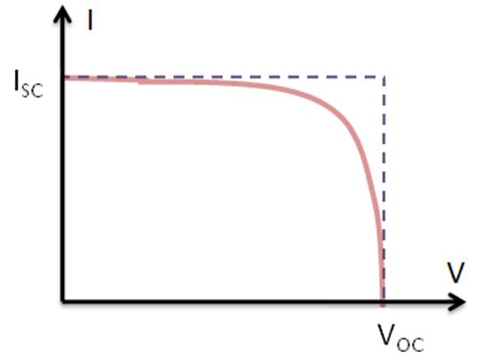
When no load is applied electrons build up until they can no longer move across the p-n junction. This is the largest difference in charge between the positive and negative leads of the cell. Open circuit voltage is the voltage difference that exists between the two leads at this point, the highest voltage the cell can possibly produce.
Conversely when there is an easy, no resistance, path between the two leads there is maximum electron flow between them. Short circuit current is the highest current the cell can produce, when there is no resistance between the positive and negative poles.
When electrons move freely there is no voltage between the two poles, when electrons do not move at all there is no current. For any real load the voltage and current will be less than these two maximum values but greater than zero.
Several factors can reduce the power output of a cell. Over time radiation increases the internal series resistance of the cell, which degrades the fill factor. Since the solar cell degrades over time when preparing for a space mission we can't just consider the power production at the beginning, we have to consider the end of life (EOL) production. The degradation ratio, ratio of end of life to beginning of life (BOL) power production is usually about 0.7 to 0.9.
Temperature also reduces power efficiency. Most solar cells give their efficiency at 28 degrees Celsius. As temperature increases efficiency decreases at a rate of 0.025% - 0.075% per degree C. Since spacecraft temperatures can vary dramatically this is a serious concern.
Area power density of a solar array assumes direct sunlight. If the sunlight comes in at an angle less power is produced. At a high angle of incidence no power at all is produced. The rate of electrical power produced by a cell based on solar power incident:
Solar conversion efficiency, seen above, is the ratio of electrical power out to solar power in given best case conditions. A single p-n layer cell has a theoretical maximum efficiency of 33.7%. Multiple layers can improve the efficiency. For an infinitely thick cell the theoretical maximum is 86%, called the Shockley-Queisser limit. Commercial cells are beginning to approach the 33.7% limit.
A solar array is a collection of individual solar cells linked together to produce more power. Connecting them in series (the negative lead of one attached to the positive lead of the next) produces higher voltage. Connecting them in parallel (positive leads all connecting one end of the load, negative leads all connecting to the other) produces more current.
Remember, though, that a cell produces power based on its angle to the sun. If there's no light on the cell it produces no power. So how the cells are mounted on the vehicle matters.
One method, called body mounting, is to simply cover the exterior of a (usually circular) spacecraft in solar cells. Such a method is often combined with a dual-spin stabilization system. Although body mounting ensures that the solar array produces the same power no matter where it points, it also means that much of the array isn't producing any power at all. In fact on 1- pi-th (1/pi) of the array is producing electricity. The rest is shaded or at two high an angle of incidence to contribute. This means a lot of wasted mass on non-producing solar cells.
To reduce the mass of unneeded cells sun tracking systems are used. Much like the sun-trackers we talked about for attitude control, these sensors follow the sun. The sun tracker ensures the solar array is always pointing directly at the sun. While this reduces the mass of arrays, is requires complex control and pointing systems and a large number of moving parts. For small spacecraft this can be significantly higher than the extra mass of extra solar cells.
Solar cells have another limiting factor: the amount of sunlight available. As a spacecraft moves closer to the sun the light becomes more intense and more power is produced. Further away there is less power available. Deep space probes exploring the outer planets cannot rely on solar power, another method is needed. Radio-isotope thermal generators (RTG's) produce electricity using the decay of radioactive material. They are used any time a long mission cannot rely on solar power, whether because of distance or because it is on the dark side of a body.
Radioactive materials decay, or break down, over time. During decay a heavy atomic nucleus breaks down into two or more lighter ones. The lighter nuclei move off with some energy. As decay products collide they produce heat. RTG's convert that heat into electricity.
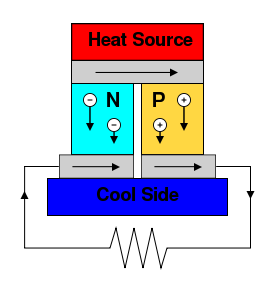
RTG's use thermoelectric generators to convert heat into electricity. A thermoelectric generator uses p and n doped semiconductors. When heat is applied to an n-doped semiconductor it pushes electrons toward the cool side. When the same thing is done to a p-doped semiconductor the positive "holes" move. Linking the two together creates a voltage difference between the positive and negative sides:
For an RTG the heat source above is a radioactive isotope. During the mission the isotope decays into stable nuclei, which produce no heat. Because of this there is a steady decline in the power output of the RTG, less radio-isotope means less heat means less power. Fuel degradation is the primary reason for EOL power production being less that BOL for RTG's, although radiation damage of the thermoelectric generator is also a concern.
The General Purpose Heat Source was developed by NASA as the standard RTG heat source. It uses plutonium-238 as fuel contained in iridium cladding for safety. Plutonium-238 (not to be confused with plutonium-239, which is used in nuclear weapons and fission reactors) has a half-life of 88 years, which ensures that it decays at a rate that produces enough heat to produce power, but not so fast that it is spent before the mission ends. Each GPHS module produces 250W of thermal power BOL.
Nowhere in the GPHS or in a thermoelectric generator are any moving parts, producing very high reliability since there's nothing to wear out. However they aren't terribly efficient, producing almost nine times more heat than electricity. Some proposals call, instead of thermoelectric generators, Stirling cycle engines for higher efficiency, but this is still under development.
Both solar cells and RTG's are used for very long missions. Neither produces very high specific power, electrical power produced per unit weight (kW/kg). To produce a large amount of power requires a very large mass of solar cells or RTG's. Many short missions have high power needs which must be accommodated without requiring much mass or space. Current space rated solar cells produce 77 W/kg, the Space Shuttle's fuel cells produced closer to 98 W/kg and required less space and less hardware.
Fuel cells are a type of electrochemical cell, similar to a battery (which we'll discuss next), which produce electricity from a chemical reaction. In a fuel cell two different chemicals are used, fuel and oxidizer, just like the chemical rockets we looked at before.

An individual fuel cell produces about 0.8 - 1.2 volts. Multiple fuel cells connected in series to provide higher voltage is called a stack. Fuel cell stacks are used to provide anywhere from 1-5 kW for periods of up to a month. Since the fuel cell stack is designed to produce a specific amount of power they are easy to scale up. Increase the size of the fuel tanks and you increase the operating life, no additional fuel cells or hardware is necessary. Fuel cells also use the same reactants as many rocket systems, no extra tanks are necessary. For manned missions fuel cells even produce drinkable water. They were used on every manned NASA mission from Gemini to the Shuttle.
Fuel cells are one form of electrochemical cell. Another that we're all familiar with is a battery. In a battery two different metals are immersed in electrolyte, an acid.
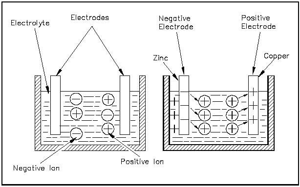
Anode and acid react to form positively charge ions and electrons, cathode and acid react to form negatively charged ions leaving positive "holes" in the cathode. Ions move freely through the electrolyte from one electrode to the other. The presence of electrons on one electrode and positive holes at the other produces a voltage difference. When a load is connected between them the electrons move across it, creating current. As the battery discharges the formation of ions reduces the acid content of the electrolyte, degrading the production of additional ions.
In primary batteries this flow is one way, they produce power only. Secondary, or rechargeable, batteries can be reverse. When a current is applied to the battery the poles are reversed and ions flow in the opposite direction, reforming acid.
Over time, even if no load is applied, there is some ionic motion which reduces the stored energy in a battery. Self discharge limits the available charge in batteries that are not occasionally recharged, and can be an important factor in reducing the useful life of primary batteries. It is not, however, usually a significant factor in the useful life of secondary batteries.
The lifetime of primary batteries is based on how much charge they contain. Secondary batteries are measured by their cycle life, the number of charge-discharge cycles they can go through before they break down too much to be recharged again.
To extend the cycle life of a battery we can reduce the depth of discharge. Depth of discharge is simply the percentage of stored charge that is expended during one discharge cycle. High depth of discharge reduces the cycle life. Because the most important factor for secondary batteries is cycle life usually they are made with higher capacity than necessary, to reduce the depth of discharge. This trend causes secondary batteries to have a lower specific power than primary batteries.
Primary batteries are used for very short discharge, low power requirement tasks. They're used for launch vehicles and pyrotechnics, and on some small satellites with very short missions or low power requirements. However the short lifetimes and low power production of primary batteries means that they are rarely used as the main source of power for a large satellite.
Secondary batteries, however, are present on almost all spacecraft. They're used as a supplement to the main power source. Secondary batteries provide power when solar arrays fall into eclipse, when the earth blocks their view of the sun. How long and how often a spacecraft is eclipsed depends on its altitude. Low orbiting satellites have very short charge-discharge cycles. Secondary batteries also provide power stability. RTG's and solar arrays don't provide the exact same current constantly during use, it fluctuates slightly during use. Batteries are used to absorb power spikes and substitute when power is low.
Another method of power storage is a flywheel. Where batteries store power in the form of chemical energy, flywheels store power as rotational energy. A flywheel is a rotating mass connected to a motor/generator. It spins up to store power, and the generator taps that rotation to regain it. Flywheel can double as momentum wheels, or two counter-rotating (rotating in opposite directions) flywheels can be used to prevent changing the vehicle's orientation. Flywheels can potentially offer higher specific power than batteries, better efficiency, and prevent self-discharge losses. However the presence of moving parts adds components that can break down and small frictional losses.
When power is stored some method is needed to connect the spacecraft loads, the energy storage, and the power source. The power distribution system is responsible not just for connecting all the components, but also for power conditioning. Power conditioning is the process of ensuring that the voltage and current is within the operating limits of the systems that require power.
When the power distribution system includes no active components it's called a direct energy transfer (DET) system. DET systems use passive power controllers, either in series or parallel. A shunt is a parallel controller, it bleeds off excess current. A series controller controls voltage directly, but both accomplish the same task.
In an unregulated DET system the battery, shunt, and load are all connected in parallel. In this kind of system the control is very simple. If the voltage from the cell is greater than the voltage from the battery then it charges the battery. If it is less then the battery discharges the difference. In this kind of system the voltage can never be less than the voltage of the battery. unregulated DET requires that most of the power conditioning is done at the loads themselves. It's usually favored for systems with short charge-discharge cycles or on spacecraft with a small number of loads requiring a great deal of power.
Regulated DET systems have additional battery charge and discharge controllers. These ensure that the battery only charges or discharges when called for. Though more complex than unregulated systems they provide more flexibility and are preferred on most large spacecraft.
There are non-DET systems. These systems have active controllers between the primary power source and the loads. One method used on solar arrays is peak-power tracking. Peak power tracking adjusts the voltage and current coming out of the solar cell so that the fill factor is always the highest it can be. While this means the highest efficiency and power output, it means the voltage changes as the power available from the cell changes. It speeds how fast batteries charge and reduces solar array area, but it increases complexity of the power distribution system.
When all systems accept the same input voltage and current the power conditioning is said to be centralized, only one power conditioning unit (PCU) is necessary. Such a setup is ideal for unregulated DET systems. However most off-the-shelf components have different requirements. It's often easier to incorporate multiple PCU's at the loads, a decentralized system.
This is very educational content and written well for a change. It's nice to see that some people still understand how to write a quality post!
ReplyDeletetks industrial co