Every system and component on a spacecraft has its own range of
operating temperatures. Outside of this range it either breaks or simply can't work properly. The duty of the thermal control system is to keep all the components within their allowable operating range. An earth orbiting spacecraft can be subjected to skin temperatures from -270 to 2,000 degrees centigrade. No component on board can handle that. Reasonable operating ranges for spacecraft components:
- electronics: -10 to 45 deg
- batteries: 0 to 10 deg
- IR detectors: -269 to -173
- solid state particle detectors: -35 to 0
- motors: 0 to 50
- solar panels: -100 to 125
Each of these components produces heat, and heat comes into the spacecraft from outside. Before we move on we must first discuss what we mean by
heat and
temperature, because they are not the same thing.
Temperature is a measure of how much energy is stored in a substance. The atoms making up a substance are constantly in motion, in fluid they move around each other freely, in a solid they vibrate in place. Temperature measures how much they move around, how quickly they flow past one another or vibrate.
Heat is a means of transferring that energy. When something cools it releases heat it gives up some of that energy it contained. When a substance is heated heat enters it and the motion increases.
An object can produce and release heat at the same time. If it releases more heat than it produces then it cools, and temperature goes down. If more heat comes in, or is produced, than leaves then the temperature goes up. When the two are exactly equal the temperature remains constant, and we say the object is in
thermal equilibrium.
That's where we want to keep our spacecraft systems, holding steady at their operating temperatures. In addition to producing heat inside an object, heat can be transferred in three different ways.
Conduction occurs inside a substance. The motion of atoms causes them to collide with each other, spreading their energy. You can see this very clearly if you try to grab a metal bot handle. Metals are good heat conductors, they transfer their energy easily. Conduction occurs when one part of an object is hotter than another and stops when the whole object is the same temperature. Conductivity is the measure of how easily an object transfers heat, heat transfer rate depends on that and the difference in temperature along the length of an object. For a rod with a cross-section A:
 Convection
 occurs when a fluid passes over a solid wall. At the surface conduction happens at a tiny scale between the two, and also occurs in each substance away from that surface. We call the whole effect together convection. Convection depends on the temperature of the fluid and the wall, as well as the transfer constant between them:
")
Convection also happens inside a fluid when heat in one part of the fluid causes it to move. Convection causes hot fluid to move up, or away from walls, because it is less dense and less viscous.
Radiation occurs in all substances, solid or fluid. Atoms in a substance have energy from their temperature. In addition to motion some of this energy
excites the atom, changes the energy level of its electrons. If the energy is so great they leave the atom it's called
ionizing the atom and if that happens to the whole substance it becomes a
plasma. But more often the electrons are excited for a short time and then fall back to where they were. When that happens they release electromagnetic radiation, or a photon. At higher temperatures the energy of the photon emitted increases. At first its invisible infra-red light, most heat stays here. But as the heat increases it can raise to the visible spectrum. If you've ever seen a piece of iron or steel in a forge or furnace you've seen this effect. Red hot steel is hot enough that it radiates in the visible red spectrum. As it becomes hotter it starts releasing yellow light in addition to the red, so it looks orange. Even hotter and it releases higher frequencies too, which together makes it look white. Iron is literally glowing hot, it's producing light, when it is red or white hot.

Radiation output of a substance depends on its surface area and temperature, obviously. These are related to the radiative heat output by the
Stefan-Boltzmann Constant (the Greek letter sigma) and a material property known as the
emissivity (Greek letter epsilon). Emissivity is the ratio of how much radiation a substance could put out, to how much it actually puts out. It ranges from zero to one. An object with an emissivity of one is called a
black-body, a perfect radiator often used in physics as an ideal model. At zero the body doesn't radiate at all, which also doesn't happen in real life, though some objects come close to one extreme or the other.
Bodies don't just emit heat radiation, they also absorb it. The ratio of how much heat comes in to how much heat the substance absorbs is the
absorptivity:

Besides absorbing the radiation the substance can also reflect some back into space and transmit some through it. The ratio of how much transmitted through is called
transmissivity, the ratio of how much is reflected is called
reflectivity.
Incoming can only do these three things, be absorbed by the material,
reflected back by it, or transmitted through it. So all three terms
must add up to one:

A spacecraft usually isn't in contact with any other solid object, or moving through a fluid. The only means of heat transfer between the spacecraft and its environment is radiative.
Environmental heat sources for a spacecraft in low earth orbit begin with the sun.
Direct sunlight is the greatest source of heat, averaging around 1358 watts per square meter of skin exposed to it. Some sunlight is indirect. When sunlight comes to earth some is absorbed and some reflected (it's too thick to transmit light well) earth's
albedo reflects that light. The amount of heat coming from earth's albedo varies drastically depending on position, a value used to design for is about 407 watts per square meter. Finally some of the heat from earth has nothing to do with the sun. Earth, after all, has temperature and radiates like any other body. For a spacecraft in LEO
earthshine accounts for 237 watts per square meter. Unlike direct sunlight or albedo this is constant, earthshine doesn't depend on position. The side facing earth always experiences this, while direct sunlight ceases whenever the spacecraft is eclipsed by the earth. During eclipse one side is subjected to earthshine and the other has no incident heat.
So we need some method of limiting, or at least evening out, the environmental heating a spacecraft is exposed to. We call means of controlling heat into the spacecraft
external thermal control.
One method is to simply prevent any one side from facing the source of heat for too long. When the spacecraft is on the day side of the earth one side is facing the sun at over 1300 watts per square meter, the other side is exposed to less than a fifth from earthshine. By simply rotating the spacecraft in roll which side is constantly changing. This method, popularly known as the
barbecue roll. It takes time for the spacecraft to heat up when exposed to the sun, rotating the spacecraft prevents any one part from getting that time. As it's facing a colder direction is is radiating that heat out.
A barbecue roll can slow the skin of the spacecraft heating up. But we still worry about heat passing through the skin, to the more heat sensitive components. Temperature sensitive components are covered by insulation to prevent heat from getting to them.
Multi-layer insulation (MLI) is the common method. MLI is, as the name implies, composed of many thin layers of insulation protecting the spacecraft, each with low transmissivity. Multiple layers are used because the radiation between layers is much slower than the conduction through a single thick layer. Inner layers usually use Mylar and Kapton sheets, for their excellent insulating properties. Outer layers are chosen for the expected operating range and durability. Each layer is separated by a mesh or fine netting and coated in a fine layer of vacuum deposited aluminum, to increase its reflectivity and absorptivity.
Like any blanket these not only keep heat out when the outside is too hot, they can also keep heat in when the outside is too cold. Both these techniques keep the spacecraft temperature stable and even. For many small spacecraft that's all that's necessary, preventing too much heat from getting in or out keeps the components in their operating ranges. However often some components have very narrow ranges or wildly different ones. When we worry about the heat produced inside the spacecraft being too much then we have to include
internal thermal control systems.
When you think about cooling something many times the first thought is to use water or ice. A variation on that idea is
ablative cooling. An ablative
coating is one that rests on the component and melts or evaporates.
Instead of increasing the temperature of the component all the heat goes
into melting or evaporating the coating.
Coating that
evaporates, of course, is gone and can only be used once. But one
closely related method is to use wax. Heat melts the wax when the
component is on, the wax radiates that heat away and cools. When cool
the wax settles and solidifies. When the component turns back on the
wax melts again, absorbing all the heat. Obviously this is only useful when the component is turned on and off in a cycle, it's no use for always on components.The easiest way to remove heat from a component that produces too much is to simply add a large mass to absorb that heat.
Heat sinks are pieces of metal that conduct heat away from the source. Instead of increasing the temperature of the component the heat goes into the heat sink.
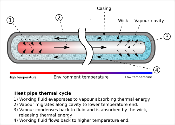
Another kind of heat sink is a
heat pipe. Unlike the heat sink this time the method of moving the heat isn't a solid, but a fluid. A heat pipe is a hollow tube filled with a fluid (called the working fluid) that is near its evaporation temperature. Near the source of heat the fluid evaporates. Gas is less dense and less viscous than liquid, so it is pushed into the center of the pipe. The hot gas wants to expand, so it pushes its way through the tube to the cold end. Here is gives up its heat and condenses. The hot gas coming in pushes the liquid back towards the hot end.
Heat pipes are themselves a particular variant of a
fluid loop. Heat pipes are a passive fluid loop, generally when we refer to a fluid loop, though, we mean an active loop. In this case it isn't evaporation pressure than causes the working fluid to move, but rather compressors and pumps. The fluid starts out cold, it moves past the hot component and absorbs that heat. Fluid is now hotter than it was, moving faster, with more energy. It then passes through a cold dump, where it loses that energy. At its very simplest that's all there is, just like the heat pipe.
Fluids used for spacecraft cooling vary. Some use ammonia, or even common refrigerant used in air conditioners and refrigerators. Spacecraft that have components with very low temperature requirements, like IR cameras, need something colder: liquid helium.
DeWar flasks contain liquid helium, which is produced by putting helium gas under pressure until it is forced into a liquid. Condensing causes it to release its heat, cooling to very low temperature. Old spacecraft released their helium as they used it, their lifespan limited by the size of the flasks. As compressors have gotten smaller and more efficient new spacecraft can recycle helium into a fluid loop. The system compresses the helium at the end of the loop to re liquify it, and the limit to its lifetime is the life of the compressor parts.
No matter which of these systems we use we have to do something with the heat once we've removed it from the systems. We need to have some method of
heat rejection. Heat rejection is how we release heat from the vehicle into space, the opposite of environmental heating.
Again often on earth when we think about getting rid of heat we think of water. Water evaporates taking the heat with it. On a spacecraft we use a similar idea, called a
flash evaporator. We mentioned it before, one of the early method of using DeWar flasks. Fluid moves past the heat source, taking heat with it. Heated fluid is dumped overboard, removing heat from the spacecraft. Though effective this obviously has a limited lifespan, and is primarily used to remove excessive heat for short periods of operation, not as a long-term method of heat rejection.
Just as the only way heat can enter the spacecraft is radiation, so too the only way a spacecraft can release heat is through radiation. We use
radiators to reject heat from a vehicle into space. Radiators are just panels, either on the skin of the spacecraft or out from it, with large surface area exposed to space. Most of our internal thermal control systems remove heat from a hot source to a cold source, the radiator is that cold source. They can be the opposite end of the heat sink, heat pipe, or fluid loop.
Radiators have to emit heat, but we don't want them to absorb it. We want our radiator to have a low
absorptivity to emissivity ratio. A way to improve that ratio is the use of a
second surface reflector. This is a two layer radiator. The top layer is a high emissivity, but is also transparent. The lower layer has a high reflectivity. Incoming radiation is reflected by the second layer and passes back out. Heat is passed from the second layer to the outer one by conduction, in essence we get the emissivity of one layer and the reflectivity of the other.
Now, radiators are good for removing heat from the spacecraft. Sometimes, though, we don't want them to. After all the heat coming in changes, sometimes we might not want to radiate heat.
Louvers allow us to control the emissivity of the radiator. Louvers are rotating vanes that can be open or closed. When open they expose a radiator below them to open space, when closed they reflect that heat back into the spacecraft. Open louvers make a radiator with high emissivity, closed louvers make one with low emissivity. If the louvers are closed the spacecraft retains more heat, if they are open it emits more heat.
So we can remove heat from a component and we can reject heat into space. But we don't just have one component in a spacecraft, we have many. And each has a different operating range, and each produces a different amount of heat. Fluid loops don't just go from hot reservoir to cold reservoir, there are many heat sources. So we start with the component that has the lowest operating regime and we take the fluid there first, when it is coldest. We move fluid from place to place in order of how much heat it must remove. If we have a component that must be heated in order to work we might add a heater to it, or we might add it after the working fluid has heated up. If the fluid is warmer than the component then it will warm the component instead of cooling it. Then the working fluid goes to a radiator and compressor and moves along the loop again.
For most spacecraft that is where environmental control ends. The only important environmental factor is temperature. However sometimes we don't just have electronic components and cameras on a spacecraft, sometimes we have people on board too. Manned missions introduce a number of new challenges.
First the
habitat, where the crew works and lives, must be in the proper temperature range. The human comfort zone stretches from 15 to 20 degrees centigrade, though people can tolerate much greater extremes, most people enjoy a room temperature of right around 21 degrees. The habitat also must provide all the necessary requirements for human life.
Let's consider a crew member a device which, in addition to doing work, converts input materials into output. An average human being consumes 840 grams of oxygen, 3,520g of water, and 620g food each day. Simultaneously he produces 1,000 grams of carbon dioxide, 2,280g of moisture, and 170g waste. All these outputs must be removed or otherwise dealt with while we supply all the inputs.
Air is the most obvious. For short duration flights we can often ignore food and water, waste, and other problems, but we can never ignore oxygen. A person needs at least 14 kPa of oxygen (that is the pressure of pure oxygen, or contribution of oxygen to total pressure,
partial pressure) to survive. Below this, even in a pure oxygen environment, the body can't get enough and the person begins to asphyxiate. At most a person can tolerate 48kPa of oxygen, any more leads to oxygen toxicity, a potentially lethal problem known to deep sea divers.
We can't use pure oxygen, however. Oxygen doesn't just support life, it also supports fire. The more oxygen is present the easier it becomes for fire to exist. A pure oxygen environment contributed to the Apollo 1 fire, killing three astronauts during an early pad test. On Earth we live in a low oxygen environment, only 20% is oxygen. The rest is mainly nitrogen, so that's what we do in space. Nitrogen is nonflammable and largely nonreactive, so we make our spacecraft atmosphere 80% nitrogen to reduce combustibility.
Some spacesuits use a pure oxygen feed, it reduces the pressure and makes them easier to move it. However it also requires almost an hour of pre-breathing for astronauts before performing an extra-vehicular activity (EVA). Using the same concentration as the habitat relieves this requirement, but reduces the astronaut's mobility in the suit.
For missions lasting more than a few hours we also have to worry about the crew getting food and water. A human drinks 2 liters of water each day, and when we include things like washing and bathing that quickly increases to 20L. Spent water can be recycled for washing, known as
grey water, but drinking water must be fresh and clean. Recall that fuel cells produce water as a by product, this is one possible source of clean water for the crew to drink. Otherwise we have to carry it.
Likewise we have to carry food. Often astronaut food is freeze-dried to save space and to extend its shelf life. With packaging the minimum amount of food can easily increase to 2kg per day per person that must be carried into orbit.
Once the astronaut has completely finished with the food there is waste that must be dealt with. At one time
intimate contact devices were used. This is a polite term for diapers and even more uncomfortable bags and tubes placed over or in the appropriate body parts. Now suction toilets are used. Suction doesn't work nearly as well as gravity and can be uncomfortable for all involved. Typically the waste is jettisoned to burn up in the atmosphere once removed. Sometimes it is collected and returned to Earth for analysis by flight medics.
That isn't the only form of waste produced by the human body. People also produce moisture in the form of sweat and released by breath. People produce heat. These must be removed from the environment, as in space there's no reason for hot air to move as their is on Earth. Fans are used to circulate air and force air through filters to remove hairs, skin cells, and moisture.
People also flood the air with carbon dioxide, which must be removed so they can continue to breathe.
CO2 scrubbers remove carbon dioxide from the air. On the shuttle scrubbers known as LiOH canisters were used. Lithium-hydroxide chemically reacts with carbon dioxide, removing it from the air. After a while the canister becomes saturated and can no longer remove CO2 from the air, and the canister must be replaced. The ISS uses the US made Carbon Dioxide Removal Assembly (CDRA) and the Russian made Vozdukh. Both of these systems remove carbon dioxide from the air and vent it into space.
All the systems we've talked about just now are open loop systems. In the beginning we input food, oxygen, and water; in the end we remove carbon dioxide and waste. But we need to store or carry those inputs and the outputs are useless to us. A closed source system would recycle the outputs back into new inputs. There is a device here on Earth we're all familiar with that converts carbon dioxide into oxygen at the same time as it converts waste into food and filters water. It's called a plant. These amazing devices cannot yet be carried in space effectively and used as a life support mechanism. It isn't possible yet to fully anticipate how complex an ecosystem needed so support large scale growing is, nor is there room in on the ISS, or any flight, for agriculture. Though a simple and obvious solution,
bioregnerative life support is still on the drawing board.


")


